
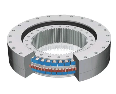
Three Row Roller Bearing Internal Gear
The three row roller slewing bearing has three seat rings,which separate the upper,lower and radial raceways,it made each row of the roller's load capacity can be specified and can bear different loads simultaneously. The capacity load is the largest one compare with the other three models.Due to the large size in axial and radial dimension the solid structure, it is specially suitable for the heavy duty machinery such as wheeled excavator,wheeled crane, ship crane,ladle turrets and the heavy duty mobile crane etc.
Weight/KG: 224-7320
Note: 1. N1 is the numbers of lubricating holes. Oil cup M10×1JB/T7940.1~JB/T7940. 2. The Oil nipple's location can be change according to the user's application. 2. n-φ can change to tapped hole, the diameter of tapped hole is M, and depth is 2M. 3. The tangential tooth force in the form is the max tooth force; the nominal tangential tooth force is 1/2 of the max one. 4. "K" is addendum reduction coefficient.
No.
Inxternal Gear
DL
mmDimensions
Mounting Dimension
Structural Dimension
Gear Data
Gear circumferential force
Weight
kg
D
mmd
mmH
mmD1
mmD2
mmn
mm
dm
mmL
mmn1
mmH1
mmh
mmb
mmx
m
mmD e
mmz
Normalizing
Z 104NQuenching
T 104N
1
133.25.500
634
366
148
598
402
24
18
M16
32
4
10
32
80
0.5
5
337
68
5.0
6.7
224
134.25.500
6
338.4
57
2
133.25.560
694
426
148
658
462
24
18
M16
32
4
10
32
80
0.5
5
397
80
5.0
6.7
240
134.25.560
6
398.4
67
3
133.25.630
764
496
148
728
532
28
18
M16
32
4
10
32
80
0.5
6
458.4
77
6.0
8
270
134.25.630
8
459.2
58
4
133.25.710
844
576
148
808
612
28
18
M16
32
4
10
32
80
0.5
6
536.4
90
6.0
8
300
134.25.710
8
539.2
68
5
133.32.800
964
636
182
920
680
36
22
M20
40
4
10
40
120
0.5
8
595.2
75
12.1
16.7
500
134.32.800
10
594
60
6
133.32.900
1064
736
182
1020
780
36
22
M20
40
4
10
40
120
0.5
8
691.2
87
12.1
16.7
600
134.32.900
10
694
70
7
133.32.1000
1164
836
182
1120
880
40
22
M20
40
5
10
40
120
0.5
10
784
79
15.1
20.9
680
134.32.1000
12
784.8
66
8
133.32.1120
1284
956
182
1240
1000
40
22
M20
40
5
10
40
120
0.5
10
904
91
15.1
20.9
820
134.32.1120
12
904.8
76
9
133.40.1250
1445
1055
220
1393
1107
45
26
M24
48
5
10
50
150
0.5
12
988.8
83
22.9
31.4
1200
134.40.1250
14
985.6
71
10
133.40.1400
1595
1205
220
1543
1257
45
26
M24
48
5
10
50
150
0.5
12
1144.8
96
22.9
31.4
1300
134.40.1400
14
1139.6
82
11
133.40.1600
1795
1405
220
1743
1457
48
26
M24
48
6
10
50
150
0.5
14
1335.6
96
26.3
36.6
1520
134.40.1600
16
1334.4
84
12
133.40.1800
1995
1605
220
1943
1657
48
26
M24
48
6
10
50
150
0.5
14
1531.6
110
26.3
36.6
1750
134.40.1800
16
1526.4
96
13
133.45.2000
2221
1779
231
2155
1845
60
33
M30
60
6
12
54
160
0.5
16
1702.4
107
32.2
44.5
2400
134.45.2000
18
1699.2
95
14
133.45.2240
2461
2019
231
2395
2085
60
33
M30
60
6
12
54
160
0.5
16
1926.4
121
32.2
44.5
2700
134.45.2240
18
1933.2
108
15
133.45.2500
2721
2279
231
2655
2345
72
33
M30
60
8
12
54
160
0.5
18
2185.2
122
36.2
50.1
3000
134.45.2500
20
2188
110
16
133.45.2800
3021
2579
231
2955
2645
72
33
M30
60
8
12
54
160
0.5
18
2491.2
139
36.2
50.1
3400
134.45.2800
20
2488
125
17
133.50.3150
3432
2868
270
3342
2958
72
45
M42
84
8
12
65
180
0.5
20
2768
139
45.2
62.6
5000
134.50.3150
22
2758.8
126
18
133.50.3550
3832
3268
270
3742
3358
72
45
M42
84
8
258
65
180
0.5
20
3168
159
45.2
62.6
5680
134.50.3500
22
3154.8
144
49.8
68.9
19
133.50.4000
4282
3718
270
4192
3808
80
45
M42
84
8
258
65
180
0.5
22
3116.8
165
49.8
68.9
6470
134.50.4000
25
3610
145
56.5
78.3
20
133.50.4500
4782
4218
270
4692
4308
80
45
M42
84
8
258
65
180
0.5
22
4122.8
188
49.8
68.9
7320
134.50.4500
25
4110
165
56.5
78.3